Loxone MicroSD Cards

Loxone states the following on their website:

Use only Loxone SD cards for the Miniserver. All SD cards have their own CPU which manages the flash memory. For optimum performance, Loxone OS accesses many low-level functions of the SD card, unlike, for example, a digital camera.

Wow, this is exciting! What mystery low level functions are they using? Time to find out.

The server ships with a 4GB Micro SD Card, which is of the SDHC type.

SD cards exists in many different varieties, but have to follow the specifications from the SD Group. This includes the communication on the bit level, as well as how commands are executed. However, there are options to have custom commands or at least non-mandatory commands. It is also possible to only support a subset of commands for a manufacturer, if they supply specific SD cards. Loxone could do that, but it is not probable, just because it makes it really hard for them to switch vendors for their SD cards, if prices and or availability changes. You don’t want to release an update to the Miniserver for different types of SD cards.

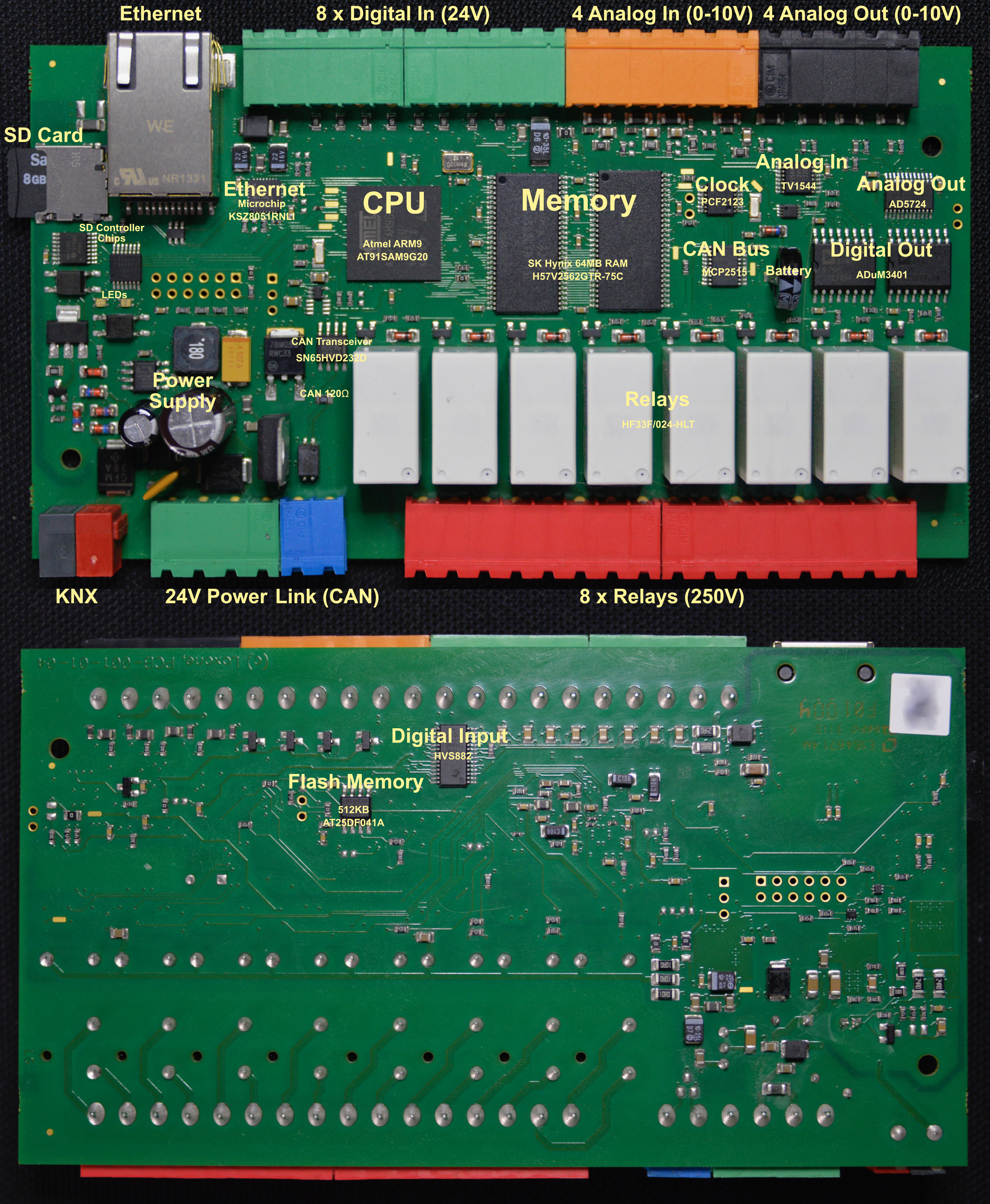
As I already looked at the mainboard of the Miniserver, it seems the CPU is talking directly to the SD card. That is not a surprise, considering that even Arduinos can do that easily. The Miniserver does that with the help of some gate logic, probably for buffering. I didn’t really care to look into the exact implementation details too much here.

Considering that the physical communication is standardized and that the actual firmware is read from the SD card by the boot code from the flash memory, I don’t expect too much special code for reading. And I am correct: the initialization phase for the SD card seems to follow the specification from the SD Group perfectly and can detect all types of SD cards up to SDHC.

The detailed information collected during initialization about the card can be requested from Loxone Config via “Detailed Device Info”:

SD-Test: SD performance read=403kB/s write=345kB/s no error (0 0), ManufactorerID 2 Date 2016/3 CardType 2 Blocksize 512 Erase 0 MaxtransferRate 25000000 RWfactor 2 ReadSpeed 22222222Hz WriteSpeed 22222222Hz MaxReadCurrentVDDmin 3 MaxReadCurrentVDDmax 5 MaxWriteCurrentVDDmin 5 MaxWriteCurrentVDDmax 1 Usage:1.71%

What does these things mean?

  • read = measured data read performance in kB/s after 1MB of reading a test file
  • write = measured data read performance in kB/s after 1MB of writing a test file
  • no error (0 0) = number of errors with this SD card (first number/error code = 0: no error, 1: read error, 2: verify error, second number: number of errors)
  • ManufactorerID (yes, that is probably an original Austrian typo) = The manufacturer of the card. The ID is assigned by the SD Group.
  • Date = Manufacturing date of the card
  • CardType = 0 = unknown, 1 = SDv2, 2 = SDHC, 3 = SDv1 – detected during initialization
  • Blocksize = 512 bytes (I think it this is true for all cards)
  • Erase = DATA_STAT_AFTER_ERASE from the SCR register. Defines the data status after erase.
  • MaxtransferRate = TRAN_SPEED from the CSD register. Maximum data transfer rate per one data line in bit/s
  • RWfactor = R2W_FACTOR from CSD register (0 = 1, 1 = 2 (write half as fast as read) , 2 = 4, 3 = 8, 4 = 16, 5 = 32)
  • ReadSpeed = 133333333 / (2 * ((133333333 / (2 * MaxtransferRate)) + 1))
  • WriteSpeed = 133333333 / (2 * ((133333333 / (2 * MaxtransferRate)) + 1)) (always identical to ReadSpeed)
  • MaxReadCurrentVDDmin = VDD_R_CURR_MIN from CSD register (0=0.5mA; 1=1mA; 2=5mA; 3=10mA; 4=25mA; 5=35mA; 6=60mA; 7=100mA)
  • MaxReadCurrentVDDmax = VDD_R_CURR_MAX from CSD register (0=1mA; 1=5mA; 2=10mA; 3=25mA; 4=35mA; 5=45mA; 6=80mA; 7=200mA)
  • MaxWriteCurrentVDDmin = VDD_W_CURR_MIN from CSD register (0=0.5mA; 1=1mA; 2=5mA; 3=10mA; 4=25mA; 5=35mA; 6=60mA; 7=100mA)
  • MaxWriteCurrentVDDmax = VDD_W_CURR_MAX from CSD register (0=1mA; 1=5mA; 2=10mA; 3=25mA; 4=35mA; 5=45mA; 6=80mA; 7=200mA)
  • Usage = How much of the SD card is used by data


The maximum supported capacity is 16GB, so do not use larger ones.

All the technical information is reported from the SD card and only for information. After initialization, what else does the Miniserver do to communicate to the card?

  • Reading blocks via Block Read (CMD17)
  • Writing blocks via Block Write (CMD18)
  • Erasing blocks by simply writing empty blocks
  • Repair after errors: power cycle the SD card and reinitialize the card (just as when the server is booting)

There are three different types of SD Card errors possible:

  • Hardware errors during reading/writing. They occur within the low-level communication with the SD card itself. In this case a repair is automatically tried.
  • CRC error. The Loxone filesystem has checksums over each block. If they don’t match, it is an error – this could potentially happen, if the SD card is defect. But the software also tries to do a repair.
  • SD card is full. The Miniserver tries to write data, but there is no more space on the SD card.

The Miniserver only uses mandatory commands, this means every single SD card in the market has to implement them. Therefore any SD card from any good manufacturer should work just fine in the Miniserver. That said: there are Chinese manufacturers who sell SD cards with a limited actual capacity (e.g. 2GB) but which identify themselves as e.g. 16GB cards. This will result in data loss!

Inside the Loxone Miniserver

I’d like to explain some technical details of the Loxone Miniserver. The Miniserver (as well as all extensions) are ARM based, just like all modern mobile phones. It is clocked at just 8MHz.

The Miniserver is ARM based. The CPU is booting from a 512kb flash memory. This code then loads the actual operating system from the SD Card into the additional 64MB of memory and executes it from there.

CPU, Flash Memory, SRAM

The CPU is an Atmel AT91SAM9G20 from Microchip. It is a 3,3V 400MHz ARM926 with 32kb internal SRAM and 64kb internal ROM. It is paired with a serial interface Flash memory (AT25DF041A from Adesto Technologies), which is updatable by Loxone – it is one of two chips mounted on the back of the board. This flash memory also contains non-volatile memory used by the Miniserver, like encryption keys, which are not stored on the SD card. The other important chips are two SD RAM chips (H57V2562GTR from SK Hynix) as additional memory with 256MBit each adding another 64MB of memory.

Ethernet

The Ethernet is connected with another Chip from Microchip, the KSZ8051RNL1. Which is a 10BASE-T/100BASE-TX Automotive Physical Layer Transceiver. It doesn’t offer a lot, so most of the load for the different protocols TCP/IP and UDP, ARP, DHCP, etc. are all handled by the CPU.

SD Card

The SD Card is accessed with some logic gate directly. Nothing special here.

RTC Clock

The Miniserver has a battery backed CMOS Real-Time Clock (RTC) via a PCF2123 from NXP Semiconductors. This allows the system to run without an internet connection, while still having a valid time. During boot it is set if possible by testing various NTP servers.

Relays / Digital Out

The Relays are HF33024-HLT, which are isolated from the CPU by two ADuM3401 from Analog Devices.

Analog Out

The Analog Out are driven by a AD5724 also from Analog Devices, which is a a complete, quad, 12-/14-/16-Bit, serial input, unipolar/bipolar voltage output DAC. They are driven to have a 10V output range with a 12-bit resolution.

Analog In

The Analog Ins are driving by a TV1544 from Texas Instruments. It is a CMOS 10-bit switched-capacitor successive-approximation (SAR) analog-to-digital (A/D) converter.

Digital In

The digital inputs are read by a HVS882 from Texas Instruments. It is an 8-channel digital input serializer, which can handle up to 34V at the inputs with a flexible current limiter – it therefore also protects the CPU from damage. This is the other chip, which is mounted on the back of the board.

Loxone Link

The Loxone Link bus is standard CAN bus connected via a CAN controller (MCP2515, also Microchip) to the CPU. It is using a standard CAN Transceiver (SN65HVD232D from Texas Instruments) to protected the Miniserver from defects on the bus. The Miniserver also has a 120Ω resistor built-in, so it has to be on the end of the CAN bus. The CAN bus is clocked at 125kHz (which allows up to 500m of cable length for the Loxone Link bus).

All packages are using the extended frame format. The identifier is therefore always 29-bit (0…0x1FFFFFFF) and the data package is always 8 bytes long. Any CAN bus monitor hardware will work just fine with the Loxone Link bus.

The Loxone Link bus is a strict Master-Slave bus. The Miniserver as the master talks to the extensions, the extensions send data to the Miniserver. Extensions never talk to each other. The Miniserver can either multicast to all extensions or to specific extensions via direct commands. In the update case, it can send the update to all extensions of a certain type at the same time.

Photo with Labels of the Mainboard

Loxone Miniserver Mainboard

Loxone UDP/HTTP Command Parser Syntax

Loxone can parse incoming data e.g. via UDP/HTTP to detect variables. I found their documentation not really good. It feels like it is almost an art to setup these parse strings, while it is actually quite simple.

The string is searched in the incoming data stream. If the full string is detected, it succeeds and returns the value (0.0 being the default). If it didn’t match the whole pattern within the stream, it resets and continues again to parse the data. Only if the whole string was parsed fully, will the matching stop.

Possible characters in the parse string

Matching individual characters

  • 7-bit ASCII characters: they are taken as-is and need to match
  • \\ matches a single \ (0x5C)
  • \n matches a LF (0x0A)
  • \r matches a CR (0x0D)
  • \t matches a TAB (0x09)
  • \xAB match a hex byte AB. This allows matching non-ASCII characters. \xAB would match 0xAB.
  • \a match a letter (A-Z, a-z)
  • \b match a TAB or space (0x09, 0x20)
  • \m match a letter or digit (A-Z, a-z, 0-9)
  • \d match a digit (0-9)
  • \. matches any byte (= skips/ignores one byte)

Matching multiple characters

  • \# match any number digits and . , or -. This should match a regular floating point number and continue after the number.
  • \w match any number of letters and digits (A-Z, a-z, 0-9). This should match a word and continue after that word.
  • \s123 skips/ignores 123 bytes in the incoming data stream. All digits following \s are using to build a number, the value can be really large – more than is ever needed.

Searching

  • \iXXX\i searches the string XXX and continues after that string with matching. The string can have standard UNIX control characters (\a, \b, \f, \n, \r, \t, \v plus the hex extension: \xAB).

Storing a value

The returned value is always a 64-bit floating point number, which can result in rounding issues for certain integer values.

  • \1…\8 stores the following byte as part of a 64-bit binary integer result. \1 is the LSB, \8 is the MSB. Sign-extension can be applied.
  • \h (hex value) stores the following ASCII-hex data (0-9, a-f, A-F) as a 32-bit MSB integer result. First invalid character ends the value. The value is returned as-is, no sign extension is applied.
  • \v (value) stores a value created from ASCII characters. Any number of spaces before the values are ignored. Then the optional sign (+ or -) can follow, plus more spaces. A &nbps; is ignored after the sign as well. The number is any number of digits (0-9) followed by (, or .) plus more digits. Then an exponent (E or e) can follow plus more digits. The first character not matching the described number will end the value. The resulting number is obviously a floating point value.
  • If \f (factor?) is part of the search term, the value will always be 0.0. This feels like a bug in the code and \f was probably thought to be a multiplication factor for the incoming value.

It is possible to have several \h and \v in the search pattern. Only the last one will be used. Same with \1, etc. If more than one \1 occurs, the first one will be ignored as well.