I’d like to explain some technical details of the Loxone Miniserver. The Miniserver (as well as all extensions) are ARM based, just like all modern mobile phones. It is clocked at just 8MHz.
The Miniserver is ARM based. The CPU is booting from a 512kb flash memory. This code then loads the actual operating system from the SD Card into the additional 64MB of memory and executes it from there.
CPU, Flash Memory, SRAM
The CPU is an Atmel AT91SAM9G20 from Microchip. It is a 3,3V 400MHz ARM926 with 32kb internal SRAM and 64kb internal ROM. It is paired with a serial interface Flash memory (AT25DF041A from Adesto Technologies), which is updatable by Loxone – it is one of two chips mounted on the back of the board. This flash memory also contains non-volatile memory used by the Miniserver, like encryption keys, which are not stored on the SD card. The other important chips are two SD RAM chips (H57V2562GTR from SK Hynix) as additional memory with 256MBit each adding another 64MB of memory.
Ethernet
The Ethernet is connected with another Chip from Microchip, the KSZ8051RNL1. Which is a 10BASE-T/100BASE-TX Automotive Physical Layer Transceiver. It doesn’t offer a lot, so most of the load for the different protocols TCP/IP and UDP, ARP, DHCP, etc. are all handled by the CPU.
SD Card
The SD Card is accessed with some logic gate directly. Nothing special here.
RTC Clock
The Miniserver has a battery backed CMOS Real-Time Clock (RTC) via a PCF2123 from NXP Semiconductors. This allows the system to run without an internet connection, while still having a valid time. During boot it is set if possible by testing various NTP servers.
Relays / Digital Out
The Relays are HF33024-HLT, which are isolated from the CPU by two ADuM3401 from Analog Devices.
Analog Out
The Analog Out are driven by a AD5724 also from Analog Devices, which is a a complete, quad, 12-/14-/16-Bit, serial input, unipolar/bipolar voltage output DAC. They are driven to have a 10V output range with a 12-bit resolution.
Analog In
The Analog Ins are driving by a TV1544 from Texas Instruments. It is a CMOS 10-bit switched-capacitor successive-approximation (SAR) analog-to-digital (A/D) converter.
Digital In
The digital inputs are read by a HVS882 from Texas Instruments. It is an 8-channel digital input serializer, which can handle up to 34V at the inputs with a flexible current limiter – it therefore also protects the CPU from damage. This is the other chip, which is mounted on the back of the board.
Loxone Link
The Loxone Link bus is standard CAN bus connected via a CAN controller (MCP2515, also Microchip) to the CPU. It is using a standard CAN Transceiver (SN65HVD232D from Texas Instruments) to protected the Miniserver from defects on the bus. The Miniserver also has a 120Ω resistor built-in, so it has to be on the end of the CAN bus. The CAN bus is clocked at 125kHz (which allows up to 500m of cable length for the Loxone Link bus).
All packages are using the extended frame format. The identifier is therefore always 29-bit (0…0x1FFFFFFF) and the data package is always 8 bytes long. Any CAN bus monitor hardware will work just fine with the Loxone Link bus.
The Loxone Link bus is a strict Master-Slave bus. The Miniserver as the master talks to the extensions, the extensions send data to the Miniserver. Extensions never talk to each other. The Miniserver can either multicast to all extensions or to specific extensions via direct commands. In the update case, it can send the update to all extensions of a certain type at the same time.
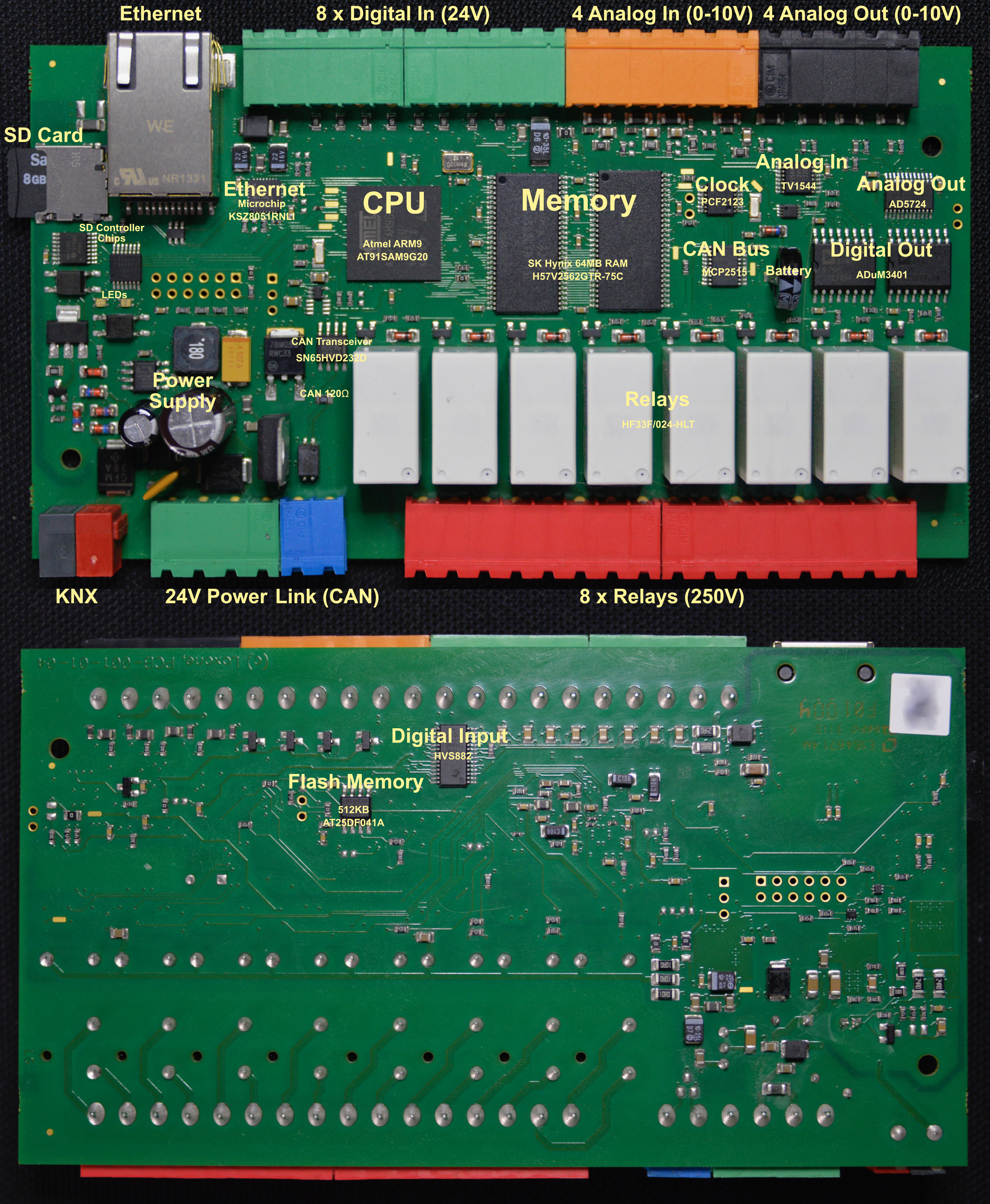
Photo with Labels of the Mainboard