
I’ve looked into a lot of the internals of the Loxone Miniserver (the CAN bus protocols, the SD card file system, etc) and written it down with a lot of sample code at https://github.com/sarnau/Inside-The-Loxone-Miniserver. For the ambitious i’ve also provided an STM32 ARM implementation of the Loxone Link/Loxone Tree protocol for a lot of hardware at https://github.com/sarnau/LoxLink
Category: Home Automation
Communication protocol of the Proteus EcoMeter TEK603
The receiver device has a USB port, which has a CP2102 USB<->RS232 converter. With 115200 baud, 8N1 it is possible to communicate with the device.
Package format
All data to or from the device is transmitted as a package.
- 2 byte header (‘SI’ = 0x53,0x49)
- 2 byte length of the complete package (16 bit, big-endian)
- 1 byte command (1: data send to the device, 2: data received from the device)
-
1 byte flags:
- bit 0: set the clock (hour/minutes/seconds) in the device on upload
- bit 1: force reset the device (set before an update of the device)
- bit 2: a non-empty payload is send to the device
- bit 3: force recalculate the device (set on upload after changing the Sensor Offset, Outlet Height or the lookup table)
- bit 4: live data received from the device
- bit 5: n/a
- bit 6: n/a
- bit 7: n/a
-
1 byte hour – used to transmit the current time to the device
- 1 byte minutes
-
1 byte seconds
-
2 byte eeprom start (16 bit, big-endian) – unused in live data
-
2 byte eeprom end (16 bit, big-endian)
-
n bytes payload
-
2 byte CRC16 (16 bit, big-endian)
The app never always read more than about 800 bytes of data at once, e.g. reading the history is done in 4 reads:
- 0x0000..0x0031 Header
- 0x0032..0x0289 Offsets
- 0x028a..0x03e5 This 365 entry history
- 0x03e6..0x06d0 ..continuation of the history
Live data
With an open connection and without significant change of the fluid level, the current level is send every 30/60 minutes (water/oil) to the computer. There seems to be no way to request it. Because the wireless transmitter only sends the data in that frequency, it probably makes very little sense.
If the level changes (refilling the tank) it updates much more often.
Live data has the following payload:
- 1 byte temperature in Fahrenheit + 40. The get the temperature in Celcius you need to calculate it like this =>
temperatureC = ((temperatureF - 40 - 32) / 1.8) - 2 byte sensor level in cm (16-bit, big-endian)
- 2 byte usable capacity in l (16-bit, big-endian)
- 2 byte full capacity of the tank in l (16-bit, big-endian)
EEPROM content
The EEPROM has three distinct areas:
- Header and configuration
- tank air space table (liters of tank volume based on the level above the fluid (0..300cm))
- 365 days of average usage – a round-robin buffer
Header and configuration
If there is no description, the value is unknown.
- 0x00: 0xcc (204) Magic byte, always checked to test the communication with the device.
- 0x01: 0x18 0x3D 0xff 0xca
- 0x05: 0x03 Type of the tank A..D (0..3) The tank offset table is calculated by the device based on the setting (A-C). If the table is modified via a computer, the type is set to D (3).
- 0x06: 0x0096 Height of the tank in cm (here: 150)
tankHeight - 0x08: 0x0048 Width of the tank? (Probably entered during configuration)
- 0x0a: 0x0064 Height of the tank without the rounding? (Probably entered during configuration)
- 0x0c: 0x2710 Volume of the tank (10000l)
- 0x0e: 0x01
-
0x0f: 0x00
-
0x10: 0x00
- 0x11: 0x00 0/1 Alarm Off/On
- 0x12: 0x01
- 0x13: 0x002d 45 Index to todays entry in the history
historyIndex. Because the history starts yesterday, you need to start with the next index for yesterday. - 0x15: 0x02
- 0x16: 0x00
- 0x17: 0x43
- 0x18: 0x00
- 0x19: 0x34
- 0x1a: 0x00
- 0x1b: 0x3a
- 0x1c: 0x05db (16-bit, big-endian, cost of fuel: 0.00 – 15.00 currency/l)
- 0x1e: 0x00
-
0x1f: 0x00
-
0x20: 0x00
- 0x21: 0x00
- 0x22: 0x00
- 0x23: 0x00
- 0x24: 0x00
- 0x25: 0x00
- 0x26: 0x00
- 0x27: 0x00 Sensor Offset
sensorOffsetin cm (0..70cm) - 0x28: 0x08 Outlet Height
outletHeightin cm (0..70cm) - 0x29: 0x1b
- 0x2a: 0x00
- 0x2b: 0x03
- 0x2c: 0x1c
- 0x2d: 0x00
- 0x2e: 0x94
- 0x2f: 0x00
- 0x30: 0x00 0xDD
Tank Air Space Table tankAirSpaceTable
The distance from the bottom of the transmitter to the top of the fluid. The table has one value per cm tankHeight – up to 300cm is supported. If the distance between the top and the transmitter is 0, the capacity is the maximum value. This table is calculated by the tank type A-C automatically, but can be customized to match any shape (tank type D). It is used to convert the level in cm into liter.
The outletHeight is an offset that is added to the level to return the volume of the tank. It can be used to define a reserve.
History
The history table is 365 entries large. Each entry is 3 bytes. It is a cyclic buffer with an index pointer in the header pointing at todays position. To go into the past increment the index and wrap around at 365 till you hit today again.
The 3 bytes have this format: 0xaa 0xbc 0xcc
- ‘aa’ changes up/down a bit, but it is also not clear what it means.
- ‘b’ also unknown. I’ve only seen values of 1 or 2 for it.
- ‘ccc’ is the average oil usage in 0,1l on that day (divide by 10 to get liters). 0 if there was no oil used on a day.
The level of the tank based on todays usage is estimated in liters as follows:
  usage = ccc / 10 - sensorOffset
  lowValue = tankAirTable[(int)usage]
  highValue = tankAirTable[(int)usage+1]
  usage = highValue + (lowValue - highValue) * (1 - (usage - (int)usage))
  usage = usage - tankAirTable[tankHeight - outletHeight]
Loxone MicroSD Cards
Loxone states the following on their website:
Use only Loxone SD cards for the Miniserver. All SD cards have their own CPU which manages the flash memory. For optimum performance, Loxone OS accesses many low-level functions of the SD card, unlike, for example, a digital camera.
Wow, this is exciting! What mystery low level functions are they using? Time to find out.
The server ships with a 4GB Micro SD Card, which is of the SDHC type.
SD cards exists in many different varieties, but have to follow the specifications from the SD Group. This includes the communication on the bit level, as well as how commands are executed. However, there are options to have custom commands or at least non-mandatory commands. It is also possible to only support a subset of commands for a manufacturer, if they supply specific SD cards. Loxone could do that, but it is not probable, just because it makes it really hard for them to switch vendors for their SD cards, if prices and or availability changes. You don’t want to release an update to the Miniserver for different types of SD cards.
As I already looked at the mainboard of the Miniserver, it seems the CPU is talking directly to the SD card. That is not a surprise, considering that even Arduinos can do that easily. The Miniserver does that with the help of some gate logic, probably for buffering. I didn’t really care to look into the exact implementation details too much here.
Considering that the physical communication is standardized and that the actual firmware is read from the SD card by the boot code from the flash memory, I don’t expect too much special code for reading. And I am correct: the initialization phase for the SD card seems to follow the specification from the SD Group perfectly and can detect all types of SD cards up to SDHC.
The detailed information collected during initialization about the card can be requested from Loxone Config via “Detailed Device Info”:
SD-Test: SD performance read=403kB/s write=345kB/s no error (0 0), ManufactorerID 2 Date 2016/3 CardType 2 Blocksize 512 Erase 0 MaxtransferRate 25000000 RWfactor 2 ReadSpeed 22222222Hz WriteSpeed 22222222Hz MaxReadCurrentVDDmin 3 MaxReadCurrentVDDmax 5 MaxWriteCurrentVDDmin 5 MaxWriteCurrentVDDmax 1 Usage:1.71%
What does these things mean?
- read = measured data read performance in kB/s after 1MB of reading a test file
- write = measured data read performance in kB/s after 1MB of writing a test file
- no error (0 0) = number of errors with this SD card (first number/error code = 0: no error, 1: read error, 2: verify error, second number: number of errors)
- ManufactorerID (yes, that is probably an original Austrian typo) = The manufacturer of the card. The ID is assigned by the SD Group.
- Date = Manufacturing date of the card
- CardType = 0 = unknown, 1 = SDv2, 2 = SDHC, 3 = SDv1 – detected during initialization
- Blocksize = 512 bytes (I think it this is true for all cards)
- Erase = DATA_STAT_AFTER_ERASE from the SCR register. Defines the data status after erase.
- MaxtransferRate = TRAN_SPEED from the CSD register. Maximum data transfer rate per one data line in bit/s
- RWfactor = R2W_FACTOR from CSD register (0 = 1, 1 = 2 (write half as fast as read) , 2 = 4, 3 = 8, 4 = 16, 5 = 32)
- ReadSpeed = 133333333 / (2 * ((133333333 / (2 * MaxtransferRate)) + 1))
- WriteSpeed = 133333333 / (2 * ((133333333 / (2 * MaxtransferRate)) + 1)) (always identical to ReadSpeed)
- MaxReadCurrentVDDmin = VDD_R_CURR_MIN from CSD register (0=0.5mA; 1=1mA; 2=5mA; 3=10mA; 4=25mA; 5=35mA; 6=60mA; 7=100mA)
- MaxReadCurrentVDDmax = VDD_R_CURR_MAX from CSD register (0=1mA; 1=5mA; 2=10mA; 3=25mA; 4=35mA; 5=45mA; 6=80mA; 7=200mA)
- MaxWriteCurrentVDDmin = VDD_W_CURR_MIN from CSD register (0=0.5mA; 1=1mA; 2=5mA; 3=10mA; 4=25mA; 5=35mA; 6=60mA; 7=100mA)
- MaxWriteCurrentVDDmax = VDD_W_CURR_MAX from CSD register (0=1mA; 1=5mA; 2=10mA; 3=25mA; 4=35mA; 5=45mA; 6=80mA; 7=200mA)
- Usage = How much of the SD card is used by data
The maximum supported capacity is 16GB, so do not use larger ones.
All the technical information is reported from the SD card and only for information. After initialization, what else does the Miniserver do to communicate to the card?
- Reading blocks via Block Read (CMD17)
- Writing blocks via Block Write (CMD18)
- Erasing blocks by simply writing empty blocks
- Repair after errors: power cycle the SD card and reinitialize the card (just as when the server is booting)
There are three different types of SD Card errors possible:
- Hardware errors during reading/writing. They occur within the low-level communication with the SD card itself. In this case a repair is automatically tried.
- CRC error. The Loxone filesystem has checksums over each block. If they don’t match, it is an error – this could potentially happen, if the SD card is defect. But the software also tries to do a repair.
- SD card is full. The Miniserver tries to write data, but there is no more space on the SD card.
The Miniserver only uses mandatory commands, this means every single SD card in the market has to implement them. Therefore any SD card from any good manufacturer should work just fine in the Miniserver. That said: there are Chinese manufacturers who sell SD cards with a limited actual capacity (e.g. 2GB) but which identify themselves as e.g. 16GB cards. This will result in data loss!
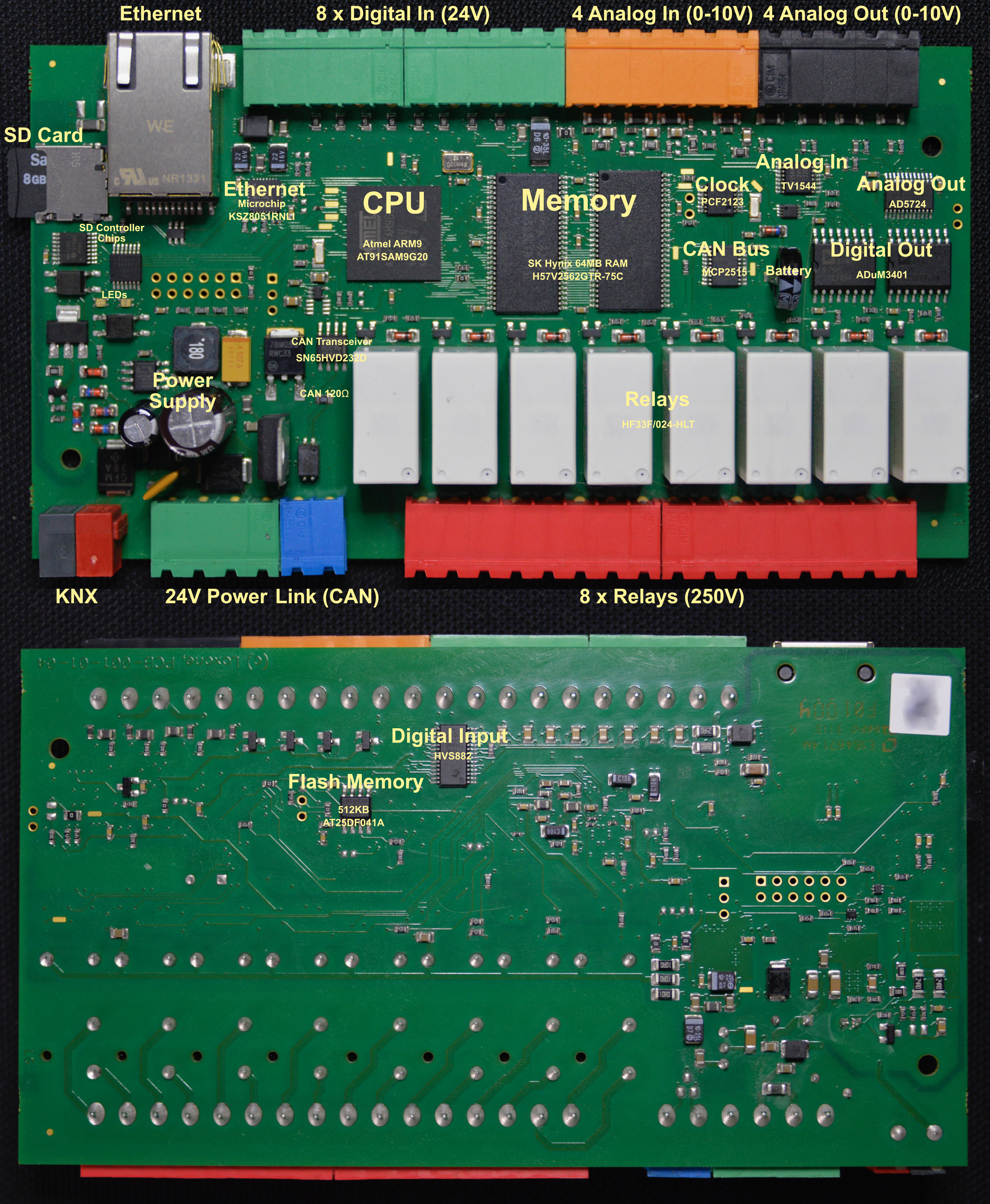
Inside the Loxone Miniserver
I’d like to explain some technical details of the Loxone Miniserver. The Miniserver (as well as all extensions) are ARM based, just like all modern mobile phones. It is clocked at just 8MHz.
The Miniserver is ARM based. The CPU is booting from a 512kb flash memory. This code then loads the actual operating system from the SD Card into the additional 64MB of memory and executes it from there.
CPU, Flash Memory, SRAM
The CPU is an Atmel AT91SAM9G20 from Microchip. It is a 3,3V 400MHz ARM926 with 32kb internal SRAM and 64kb internal ROM. It is paired with a serial interface Flash memory (AT25DF041A from Adesto Technologies), which is updatable by Loxone – it is one of two chips mounted on the back of the board. This flash memory also contains non-volatile memory used by the Miniserver, like encryption keys, which are not stored on the SD card. The other important chips are two SD RAM chips (H57V2562GTR from SK Hynix) as additional memory with 256MBit each adding another 64MB of memory.
Ethernet
The Ethernet is connected with another Chip from Microchip, the KSZ8051RNL1. Which is a 10BASE-T/100BASE-TX Automotive Physical Layer Transceiver. It doesn’t offer a lot, so most of the load for the different protocols TCP/IP and UDP, ARP, DHCP, etc. are all handled by the CPU.
SD Card
The SD Card is accessed with some logic gate directly. Nothing special here.
RTC Clock
The Miniserver has a battery backed CMOS Real-Time Clock (RTC) via a PCF2123 from NXP Semiconductors. This allows the system to run without an internet connection, while still having a valid time. During boot it is set if possible by testing various NTP servers.
Relays / Digital Out
The Relays are HF33024-HLT, which are isolated from the CPU by two ADuM3401 from Analog Devices.
Analog Out
The Analog Out are driven by a AD5724 also from Analog Devices, which is a a complete, quad, 12-/14-/16-Bit, serial input, unipolar/bipolar voltage output DAC. They are driven to have a 10V output range with a 12-bit resolution.
Analog In
The Analog Ins are driving by a TV1544 from Texas Instruments. It is a CMOS 10-bit switched-capacitor successive-approximation (SAR) analog-to-digital (A/D) converter.
Digital In
The digital inputs are read by a HVS882 from Texas Instruments. It is an 8-channel digital input serializer, which can handle up to 34V at the inputs with a flexible current limiter – it therefore also protects the CPU from damage. This is the other chip, which is mounted on the back of the board.
Loxone Link
The Loxone Link bus is standard CAN bus connected via a CAN controller (MCP2515, also Microchip) to the CPU. It is using a standard CAN Transceiver (SN65HVD232D from Texas Instruments) to protected the Miniserver from defects on the bus. The Miniserver also has a 120Ω resistor built-in, so it has to be on the end of the CAN bus. The CAN bus is clocked at 125kHz (which allows up to 500m of cable length for the Loxone Link bus).
All packages are using the extended frame format. The identifier is therefore always 29-bit (0…0x1FFFFFFF) and the data package is always 8 bytes long. Any CAN bus monitor hardware will work just fine with the Loxone Link bus.
The Loxone Link bus is a strict Master-Slave bus. The Miniserver as the master talks to the extensions, the extensions send data to the Miniserver. Extensions never talk to each other. The Miniserver can either multicast to all extensions or to specific extensions via direct commands. In the update case, it can send the update to all extensions of a certain type at the same time.
Photo with Labels of the Mainboard
Loxone UDP/HTTP Command Parser Syntax
Loxone can parse incoming data e.g. via UDP/HTTP to detect variables. I found their documentation not really good. It feels like it is almost an art to setup these parse strings, while it is actually quite simple.
The string is searched in the incoming data stream. If the full string is detected, it succeeds and returns the value (0.0 being the default). If it didn’t match the whole pattern within the stream, it resets and continues again to parse the data. Only if the whole string was parsed fully, will the matching stop.
Possible characters in the parse string
Matching individual characters
- 7-bit ASCII characters: they are taken as-is and need to match
- \\ matches a single \ (0x5C)
- \n matches a LF (0x0A)
- \r matches a CR (0x0D)
- \t matches a TAB (0x09)
- \xAB match a hex byte AB. This allows matching non-ASCII characters. \xAB would match 0xAB.
- \a match a letter (A-Z, a-z)
- \b match a TAB or space (0x09, 0x20)
- \m match a letter or digit (A-Z, a-z, 0-9)
- \d match a digit (0-9)
- \. matches any byte (= skips/ignores one byte)
Matching multiple characters
- \# match any number digits and . , or -. This should match a regular floating point number and continue after the number.
- \w match any number of letters and digits (A-Z, a-z, 0-9). This should match a word and continue after that word.
- \s123 skips/ignores 123 bytes in the incoming data stream. All digits following \s are using to build a number, the value can be really large – more than is ever needed.
Searching
-
\iXXX\i searches the string XXX and continues after that string with matching. The string can have standard UNIX control characters (\a, \b, \f, \n, \r, \t, \v plus the hex extension: \xAB).
Storing a value
The returned value is always a 64-bit floating point number, which can result in rounding issues for certain integer values.
- \1…\8 stores the following byte as part of a 64-bit binary integer result. \1 is the LSB, \8 is the MSB. Sign-extension can be applied.
- \h (hex value) stores the following ASCII-hex data (0-9, a-f, A-F) as a 32-bit MSB integer result. First invalid character ends the value. The value is returned as-is, no sign extension is applied.
- \v (value) stores a value created from ASCII characters. Any number of spaces before the values are ignored. Then the optional sign (+ or -) can follow, plus more spaces. A &nbps; is ignored after the sign as well. The number is any number of digits (0-9) followed by (, or .) plus more digits. Then an exponent (E or e) can follow plus more digits. The first character not matching the described number will end the value. The resulting number is obviously a floating point value.
- If \f (factor?) is part of the search term, the value will always be 0.0. This feels like a bug in the code and \f was probably thought to be a multiplication factor for the incoming value.
It is possible to have several \h and \v in the search pattern. Only the last one will be used. Same with \1, etc. If more than one \1 occurs, the first one will be ignored as well.
Loxone Einbindung der Termine der Stadtreinigung Hamburg
A quick Loxone Tip for People in Hamburg, Germany. That’s why it is in German…
Etwas ganz spezielles für die Hamburger Loxone Miniserver Nutzer: ein PicoC Programm, welches es erlaubt mit seiner Anschrift (Straße und Hausnummer) von der Stadtreinigung Hamburg die Termine der nächsten Abholungen einzubinden. Hamburg hat teilweise recht variable Termine und die sind auch nur ein paar Monate im Voraus als Kalender zu importieren. Mit dem Programm kann man folgendes erhalten:
In wieviel Tagen wird das nächste Mal folgendes abgeholt:
– Restmüll
– Papier
– Wertstoffe
– Bio
– Laub (nur im Herbst)
– Weihnachtsbäume (ja, haben wir wirklich – Termine gibt es nur im Januar)
Zudem gibt es Tage mit mehreren Abholungen (Restmüll und Papier oder Restmüll und Wertstoffe). Deswegen erzeugt das Programm auch einen handlichen Statustext für welche Tonnen und an welchem Tag (nächster Termin) bzw. einen Text wie “In 7 Tagen: Restmüll, Papier”.
Der Sourcecode ist einfach ins Programm Bauteil zu kopieren und STRASSE, sowie HAUSNUMMER durch die korrekte Angabe zu ersetzen.
https://gist.github.com/sarnau/6bfc02ff7a8623467f75fa558f55f72b
Loxone LoxCC Fileentpacker
Hi,
Here a quick Gist to uncompress a Loxone LoxCC file in Python: https://gist.github.com/sarnau/e14ff9fe081611782a3f3cb2e2c2bacd
Mobile Alerts Sensors
ELV is selling affordable weather sensors http://www.elv.de/ip-wettersensoren-system.html, which can be monitored via an iOS application. To allow that all data is transmitted via a gateway to a server, which the application can access. Sadly the protocol is not documented. I don’t think anybody has documented the way the URL has been constructed, especially the MD5 hash over the first part of it.
This sample code integrates sensors into fhem and I wrote it for Mac OS X, but it should work on Linux, too.
All information (and more) is available on GitHub as well.
To integrate the sensors into fhem, add the sensors to the iOS application and check if they show up. You need to note all sensor IDs. The ID is 6 bytes long and represented as a hexadecimal number. This same code supports sensors of type 2 (temperature only) and type 3 (temperature and humidity), which can be recognized via the first two characters of the ID.
You have to adjust the following things in the code:
- sensors = … Here you have to add all sensors IDs as strings
- downloadPath This needs to be adjusted to point to the log folder of fhem.
- vendorid You might want to change the UUID to a new one (just run uuidgen from the terminal)
Python Code
#!/usr/bin/env python
# -*- coding: utf-8 -*-
import sys
import os
import json
import pprint
import datetime
import hashlib
import time
downloadPath = os.path.expanduser('~/fhem-5.7/log')
pp = pprint.PrettyPrinter()
sensors = set(['021122334455',...,'031122334455'])
def parseJSON(jj):
if not jj['success']:
print '#%d %s' % (jj['errorcode'],jj['errormessage'])
return
for device in jj['result']['devices']:
#pp.pprint(device)
deviceTypeId = device['devicetypeid']
deviceName = device['name']
print '%s %s [%d] #%d %s' % (device['deviceid'], deviceName, device['lowbattery'],len(device['measurements']),datetime.datetime.fromtimestamp(device['lastseen']).strftime('%Y-%m-%d %H:%M:%S'))
year = -1
month = -1
logPath = ''
for measurement in device['measurements']:
idx = measurement['idx']
transmitTime = datetime.datetime.fromtimestamp(measurement['c'])
measurementTime = datetime.datetime.fromtimestamp(measurement['ts'])
tx = measurement['tx']
mm = measurement
del mm['idx']
del mm['c']
del mm['ts']
del mm['tx']
if year != measurementTime.year or month != measurementTime.month:
if len(logPath):
f = open(logPath, "w")
for d in sorted(data):
f.write('%s %s\n' % (d,data[d]))
year = measurementTime.year
month = measurementTime.month
logPath = downloadPath + '/S_SENSOR_%s-%d-%02d.log' % (deviceName.upper().replace(' ','_'),year,month)
data = {}
try:
for line in open(logPath).readlines():
vals = line[:-1].split(' ')
data[' '.join(vals[:-1])] = vals[-1]
except:
pass
dataKey = measurementTime.strftime('%Y-%m-%d_%H:%M:%S') + ' SENSOR_' + deviceName.upper().replace(' ','_') + ' '
if deviceTypeId == 2:
data[dataKey + 'TEMP:'] = '%.1f' % (measurement['t1'])
elif deviceTypeId == 3:
data[dataKey + 'TEMP:'] = '%.1f' % (measurement['t1'])
data[dataKey + 'FEUCHTIGKEIT:'] = '%.1f' % (measurement['h'])
else:
pp.pprint(mm)
if len(logPath):
f = open(logPath, "w")
for d in sorted(data):
f.write('%s %s\n' % (d,data[d]))
import urllib
import urllib2
devicetoken = 'empty' # defaults to "empty"
vendorid = '1FB220C4-CC15-4195-97CF-8BE4FD3DAE72' # iOS vendor UUID (returned by iOS, any UUID will do). Launch uuidgen from the terminal to generate a fresh one.
phoneid = 'Unknown' # Phone ID - probably generated by the server based on the vendorid (this string can be "Unknown" and it still works)
version = '1.21' # Info.plist CFBundleShortVersionString
build = '248' # Info.plist CFBundleVersion
executable = 'Mobile Alerts' # Info.plist CFBundleExecutable
bundle = 'de.synertronixx.remotemonitor' # [[NSBundle mainBundle] bundleIdentifier]
lang = 'en' # preferred language
request = "devicetoken=%s&vendorid=%s&phoneid=%s&version=%s&build=%s&executable=%s&bundle=%s&lang=%s" % (devicetoken,vendorid,phoneid,version,build,executable,bundle,lang)
request += '&timezoneoffset=%d' % 60 # local offset to UTC time
request += '&timeampm=%s' % ('true') # 12h vs 24h clock
request += '&usecelsius=%s' % ('true') # Celcius vs Fahrenheit
request += '&usemm=%s' % ('true') # mm va in
request += '&speedunit=%d' % 0 # wind speed (0: m/s, 1: km/h, 2: mph, 3: kn)
request += '×tamp=%s' % datetime.datetime.utcnow().strftime("%s") # current UTC timestamp
requestMD5 = request + 'asdfaldfjadflxgeteeiorut0ß8vfdft34503580' # SALT for the MD5
requestMD5 = requestMD5.replace('-','')
requestMD5 = requestMD5.replace(',','')
requestMD5 = requestMD5.replace('.','')
requestMD5 = requestMD5.lower()
m = hashlib.md5()
m.update(requestMD5)
hexdig = m.hexdigest()
request += '&requesttoken=%s' % hexdig
request += '&deviceids=%s' % ','.join(sensors)
#request += '&measurementfroms=%s' % ('0,' * len(sensors))
#request += '&measurementcounts=%s' % ('50,' * len(sensors))
http_header = {
"User-Agent" : "remotemonitor/248 CFNetwork/758.2.8 Darwin/15.0.0",
"Accept-Language" : "en-us",
"Content-Type": "application/x-www-form-urlencoded; charset=utf-8",
"Host" : "www.data199.com:8080",
}
# create an urllib2 opener()
opener = urllib2.build_opener()
# create your HTTP request
req = urllib2.Request('http://www.data199.com:8080/api/v1/dashboard', request, http_header)
# submit your request
while True:
res = opener.open(req)
parseJSON(json.loads(res.read()))
print '-' * 40
time.sleep(10*60) # wait for 10 minutes
Inside information of the Pronto IR Remote
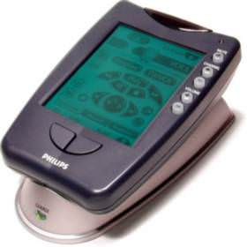 The Philips Pronto is a programmable remote control. It looks a bit like a Palm Pilot, but it is the most flexible remote control on the market (below the $1000…). The interesting thing with the Pronto is, that it is fully customizable with the Pronto Edit software.
Unfortuanlly the Pronto Edit software is for Windows only, so i reverse engineered the format of the CCF files and also tried to get information about the communication with the Pronto.
CCF file format
Source code for parsing a CCF file:
- Parse.cp (last change: 10. Nov. 1999; now with support for hidden panels, timers and beeps)
- ParseGCC.cp (last change: 12. Jul. 2001, source code for the GCC on Linux systems)
Serial Communication
Pronto has a serial port for the communication with a computer. This port works at 115200 baud, 8N1. The communication is pretty simple:
First: get attention of the Pronto. This is done by sending an ACK (0x06) to the Pronto. The Pronto should send a ‘!’ (standby mode) or a ‘*’ (awaiting data, done by holding the left and right key down, while the serial cable was plugged in). If the Pronto don’t respond, try again until timeout.
When the Pronto awaits a command, you can send strings (terminated with CR (0x0D)) like:
irlearn 3500
The Pronto now awaits an infra red signal to learn. The result is send via YModem CRC protocol.
q ccf
Inquiry. The Pronto sends a string containing 4 decimal numbers. The first is the dirty flag (CCF data in the Pronto changed by the user and is not uploaded to the computer yet), the second is the size of the CCF file, the third the the date (in a 8 digit decimal BCD format), the fourth is the time (in a 6 digit decimal BCD format) of the last change of the CCF file.
ul ccf
Uploading a CCF file from the Pronto to the computer. The CCF file is simply send via YModem CRC protocol to the computer.
dl ccf
Downloading a CCF file to the Pronto from the computer. The CCF file is simply send via YModem CRC protocol to the Pronto.
reboot
Reboot the Pronto.
Some links to interesting Pronto websites
- Philips Pronto Homepage {OFFLINE}
- Pronto Edit {OFFLINE}
- Remote Central
- Tonto A clone of ProntoEdit written in Java and therefore cross-platform